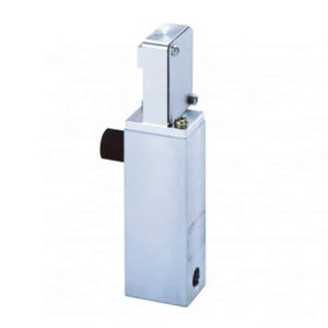
Description
Description
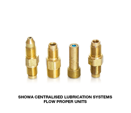
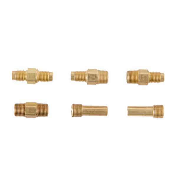
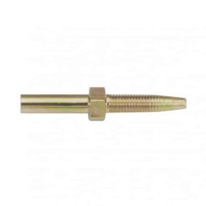
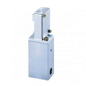
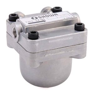
Flow Proper Units are to be installed within a resistant type system utilising the intermittent / cyclic distribution method. Flow Proper Units enable delivery of oil at a required flow rate and can be attached to Dester Units (Distribution Block) or individual lubrication points.
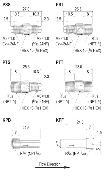
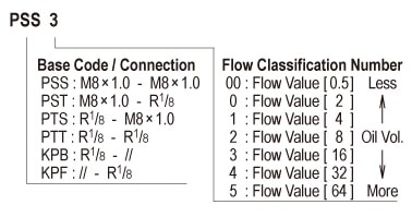
6 types of connector combinations are available, each with a selection of 7 oil flow rates. As the classification number increases a step, the flow rate doubles, allowing flow manipulation.
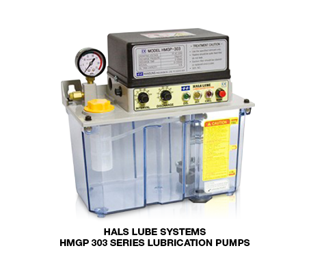
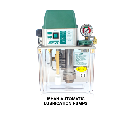
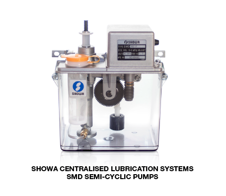
These units are to be used in conjunction with accumulative pressure type pumps (ref. page 3). Flow Proper Units are not to be utilised with volumetric type pumps, grease pumps or LA type hand pumps.
Form Code
Specification
| MODEL CODE |
Connection Size | Flow Class |
Flow Value |
Operating Pressure (MPa) |
Recommended Viscosity (m㎡/s) |
Compatible Connectors | ||
| IN | OUT | IN | OUT | |||||
| PSS Type | M8×1.0 (5/16 – 24NF) |
M8×1.0 (5/16 – 24NF) |
00 | 0.5 | 0.15~2 | 20~500 | PAN4 (PAN4H) |
PAN4 (PAN4H) |
| 0 | 2 | |||||||
| PST Type | M8×1.0 (5/16 – 24NF) |
R1/8 (NPT1/8) |
PAN4 (PAN4H) |
# | ||||
| 1 | 4 | |||||||
| PTS Type | R1/8 (NPT1/8) |
M8×1.0 (5/16 – 24NF) |
# | PAN4 (PAN4H) |
||||
| 2 | 8 | |||||||
| PTT Type | R1/8 (NPT1/8) |
R1/8 (NPT1/8) |
# | # | ||||
| 3 | 16 | |||||||
| KPB Type | R1/8 (NPT1/8) |
— | — | — | ||||
| 4 | 32 | |||||||
| KPF Type | — | R1/8 (NPT1/8) |
— | — | ||||
| 5 | 64 | |||||||
– Flow-rate doubles every increment in the unit’s flow classification number from 0 onwards. (Flow-rate of 00 is 1/4 of 0)
– Flow Proper Units are available in inch sizes. Size displayed in ( ), a “H” will be added to the end of the model code.
– The “#” displayed in the “Compatible Connectors / Parts” column indicates that any piping connector that can connect to Rc1/8 and Rp1/8 connections can be used.
– PSS Flow Proper Units for Ø3.2 pipe size are available. (PSS*K)
Drawing
